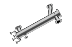
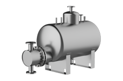
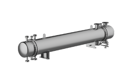
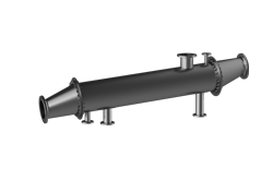
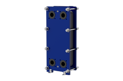
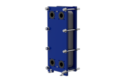
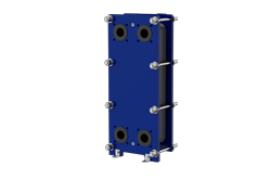
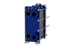
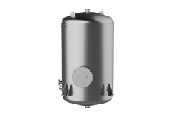
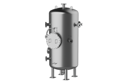
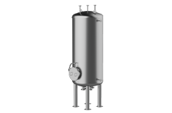
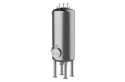
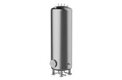
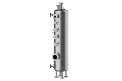
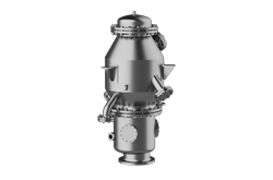
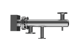
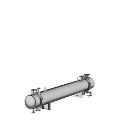
SAFETY HEAT EXCHANGER
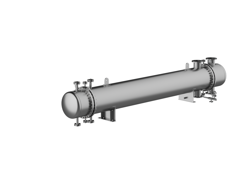
By using double tubes welded into double tube plates, ZILONIS Energy Solutions safety safety heat exchangers create a safety space that prevents contamination of the media flowing through, even in the event of a leak, and thus achieves a higher level of safety for your plant.
Description
Safety Space Created
Type GVSI:
To achieve good heat transfer in your safety heat exchanger, the inner tube is applied to the internally twisted outer tube by hydraulic expansion.
Alternatively, optimizing the heat transfer of your safety heat exchanger can also be done by using a neutral fluid in the safety chamber. If a leakage occurs in the safety heat exchanger, the pressure in the safety space increases and causes an optical or acoustic alarm signal.
The repair or renewal of the safety heat exchanger can be planned, an emergency shutdown is not necessary.
Safety heat exchanger with double tubes and double tube plate.
The design principle of ZILONIS Energy Solutions Safety Heat Exchangers prevents media mixing in case of leakage of the tube/tube sheet weld joint. By using surface-treated materials, this variant can also be manufactured as a sterile heat exchanger. During continuous operation of the safety heat exchangers, leaks due to corrosion or erosion processes are to be expected. Pipe wall breakthroughs can be the result. In such a case, the products on the tube and shell sides mix. Although leakages can be detected relatively quickly by close monitoring of characteristic analysis values, it is often necessary to shut down the plant. To prevent this, double tubes are used in the safety heat exchanger, which are rolled or welded into double tube plates. In this way, a safety space is created which prevents the mixing of the tube-side and shell-side media in the safety heat exchanger. To simultaneously reduce the resulting heat transfer resistance and thus reduce additional space requirements, the intermediate space is filled with a neutral liquid. This design is particularly suitable for coolers that are operated at relatively low temperatures.
Description
Type GVSI:
To achieve good heat transfer in your safety heat exchanger, the inner tube is applied to the internally twisted outer tube by hydraulic expansion.
Alternatively, optimizing the heat transfer of your safety heat exchanger can also be done by using a neutral fluid in the safety chamber. If a leakage occurs in the safety heat exchanger, the pressure in the safety space increases and causes an optical or acoustic alarm signal.
The repair or renewal of the safety heat exchanger can be planned, an emergency shutdown is not necessary.
Safety Space Created
Safety heat exchanger with double tubes and double tube plate.
The design principle of ZILONIS Energy Solutions Safety Heat Exchangers prevents media mixing in case of leakage of the tube/tube sheet weld joint. By using surface-treated materials, this variant can also be manufactured as a sterile heat exchanger. During continuous operation of the safety heat exchangers, leaks due to corrosion or erosion processes are to be expected. Pipe wall breakthroughs can be the result. In such a case, the products on the tube and shell sides mix. Although leakages can be detected relatively quickly by close monitoring of characteristic analysis values, it is often necessary to shut down the plant. To prevent this, double tubes are used in the safety heat exchanger, which are rolled or welded into double tube plates. In this way, a safety space is created which prevents the mixing of the tube-side and shell-side media in the safety heat exchanger. To simultaneously reduce the resulting heat transfer resistance and thus reduce additional space requirements, the intermediate space is filled with a neutral liquid. This design is particularly suitable for coolers that are operated at relatively low temperatures.
Design Principle
Application Examples
More complex, but more widely applicable, is the following technique, which is increasingly being used. Here, the outer tube is already given a twisted profile on the inside by the tube manufacturer. The corresponding inner tube is smooth on both sides and its outer diameter is approx. 1/10 mm smaller than the inside diameter of the outer tube.
After the safety heat exchanger has been assembled, the inner tube is hydraulically expanded at pressures of around 500 to 600 bar. This creates a metallic contact in the area of the swirl fins. However, the small intermediate channels remain free and allow possible leakage quantities to pass through by pressure or mirror to the interplate space and the leakage warning device of the safety heat exchanger.
There is therefore no direct risk of product mixing. More surface area is required compared to an apparatus with a conventional single tube, whereby the surface area depends on the shell-side and tube-side transition values and is therefore 50 to 100% higher. While the change in the heat transfer behavior can be calculated exactly for the system of double pipes with liquid in the safety gap, an approximate calculation is used for hydraulically expanded pipes.
It essentially relates to the portion of the transition surface that actually has metallic contact. Based on practical measurement data, it is then possible to determine this value precisely. It should be noted, however, that good transition values are reduced more in percentage terms than already moderate values of, for example, slow-flowing, higher viscosity media. The fact that possible leakages of the connection between the tube and tube plate are also safeguarded is a significant advantage of this design.
The safety heat exchangers described above are mainly used in the following areas:
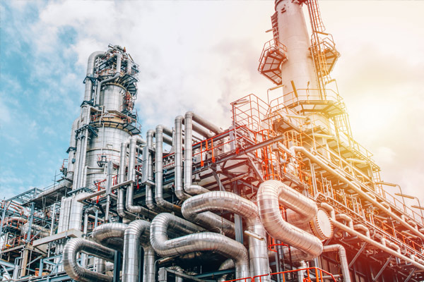
Oil coolers for highly loaded bearing lubrications as well as product final coolers in chemical plants and in refineries; due to the water-polluting nature of the media to be cooled, the mixing of product and water must be excluded.
Steam-heated service water heaters; steam penetration into the service water must be prevented, otherwise there is a risk of overheating or scalding.
Thermal oil-heated steam generators; water can spill into the hot thermal oil and vaporize explosively.
A special design, which specifically eliminates leakage of the connection between tube and tube plate, is the sterile heat exchanger, which meets FDA requirements. Double tube plates are also used in this safety heat exchanger. However, the heating surface tubes are single, as in the conventional design. The sterile heat exchanger can be used for both the U-tube design and the straight tube heat exchanger with fixed tube plates. In addition, on the product side, the sterile heat exchanger can be made of materials with high-quality surface finishes (ground, electropolished). This variant is particularly suitable for the pharmaceutical industry.
Design Principle
More complex, but more widely applicable, is the following technique, which is increasingly being used. Here, the outer tube is already given a twisted profile on the inside by the tube manufacturer. The corresponding inner tube is smooth on both sides and its outer diameter is approx. 1/10 mm smaller than the inside diameter of the outer tube.
After the safety heat exchanger has been assembled, the inner tube is hydraulically expanded at pressures of around 500 to 600 bar. This creates a metallic contact in the area of the swirl fins. However, the small intermediate channels remain free and allow possible leakage quantities to pass through by pressure or mirror to the interplate space and the leakage warning device of the safety heat exchanger.
There is therefore no direct risk of product mixing. More surface area is required compared to an apparatus with a conventional single tube, whereby the surface area depends on the shell-side and tube-side transition values and is therefore 50 to 100% higher. While the change in the heat transfer behavior can be calculated exactly for the system of double pipes with liquid in the safety gap, an approximate calculation is used for hydraulically expanded pipes.
It essentially relates to the portion of the transition surface that actually has metallic contact. Based on practical measurement data, it is then possible to determine this value precisely. It should be noted, however, that good transition values are reduced more in percentage terms than already moderate values of, for example, slow-flowing, higher viscosity media. The fact that possible leakages of the connection between the tube and tube plate are also safeguarded is a significant advantage of this design.
Application Examples
The safety heat exchangers described above are mainly used in the following areas:
Oil coolers for highly loaded bearing lubrications as well as product final coolers in chemical plants and in refineries; due to the water-polluting nature of the media to be cooled, the mixing of product and water must be excluded.
Steam-heated service water heaters; steam penetration into the service water must be prevented, otherwise there is a risk of overheating or scalding.
Thermal oil-heated steam generators; water can spill into the hot thermal oil and vaporize explosively.
A special design, which specifically eliminates leakage of the connection between tube and tube plate, is the sterile heat exchanger, which meets FDA requirements. Double tube plates are also used in this safety heat exchanger. However, the heating surface tubes are single, as in the conventional design. The sterile heat exchanger can be used for both the U-tube design and the straight tube heat exchanger with fixed tube plates. In addition, on the product side, the sterile heat exchanger can be made of materials with high-quality surface finishes (ground, electropolished). This variant is particularly suitable for the pharmaceutical industry.
INDUSTRIES

Food
Chemical And Petrochemical

Power Engineering

Building Services Engineering

Pharmaceutical
Wood and Paper
Oil and Gas
Marine
Newsletter
Product and technological news

